


| Quantity: | |
|---|---|


NOMINAL 700 × 700 MM PLANAR PROCESSING ENVELOPE Deterministic MRF Finishing for Medium-to-Large Precision Optics PKC700-Q Magnetorheological Finishing Machine A vertical multi-axis MRF platform with five controlled axes and an optional C axis, designed for corrective finishing of flat, spherical, aspheric and freeform optical surfaces. REQUEST A CONFIGURATION REVIEW |
REFERENCE CONFIGURATION |
700 × 700 mm PLANAR ENVELOPE | X / Y / Z + A / B CONTROLLED AXES | Ø150 mm STANDARD MRF WHEEL | PROJECT OPTION C AXIS |
MODULE 1 | PAIN POINTS
For larger optics, usable reach, repeatable setup and compatible metrology data matter as much as nominal machine travel.
A part may fit within the nominal planar envelope yet still require a different fixture, MRF tool configuration or setup route. Radius, sag, local slope, workpiece mass, sensor access and collision clearance all shape the practical process window.
Reach the Surface Safely Evaluate the complete optic, fixture, setup sensor and selected MRF head/wheel geometry together. | Establish a Repeatable Part Coordinate System Align centering, installed pose, tool setting, working gap and kinematic setup to the intended correction coordinates. | Keep Data and Motion Aligned Use compatible references for the error map, aperture, coordinate relationship, removal function and tool path. |
APPLICATION NOTE The nominal 700 × 700 mm planar processing envelope does not by itself define the usable clear aperture of a curved optic. |
MODULE 2 | INTEGRATED SOLUTION
The PKC700-Q combines a vertical motion platform, an MRF process module, dedicated control, process software and metrology-assisted setup functions in one structured corrective-finishing workflow.
MACHINE PLATFORM X/Y/Z linear and A/B rotary axes | MRF PROCESS Wheel/head, fluid circulation and working gap | SETUP SENSING Centering and tilt/orientation setup | CONTROL & SOFTWARE Ribbon calibration, tool setting and program checking |
STANDARD SYSTEM SCOPE • Vertical platform with X/Y/Z and A/B controlled axes • Ø150 mm MRF wheel configuration • Fluid circulation, machine control and process software • Confirmed setup-sensing hardware and station arrangement | PROJECT OPTIONS • C axis with project-defined performance and limits • Alternative MRF head/wheel configurations • Custom fixture and workpiece support • Application-specific metrology route and process package |
01 Prepare Error Data Define aperture, masks, removed terms, filtering and coordinates. | 02 Establish Removal Function Set the MRF tool, fluid-ribbon state, working gap and reference spot route. | 03 Locate Workpiece & Tool Confirm fixture datum, centering, tilt/orientation and tool setting. |
04 Calculate Dwell & Path Use the approved error map and characterized removal function. | 05 Verify Reach & Clearance Review the evaluated fixture, sensor and MRF tool geometry. | 06 Process & Re-Measure Execute, re-measure with the agreed method and iterate as required. |
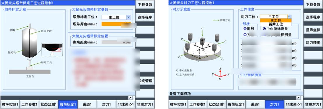
Example interfaces for MR-fluid ribbon calibration and MRF head/tool setting. Displayed values have been masked.
MR-FLUID RIBBON CALIBRATION | MRF HEAD / TOOL SETTING |
WORKFLOW BOUNDARY The screens demonstrate setup workflow only. Software version, enabled functions and project configuration are confirmed in the technical proposal. |
MODULE 3 | CORE ADVANTAGES
The PKC700-Q combines multi-axis access, metrology-assisted setup and adaptable MRF tool configurations for medium-to-large precision optics.
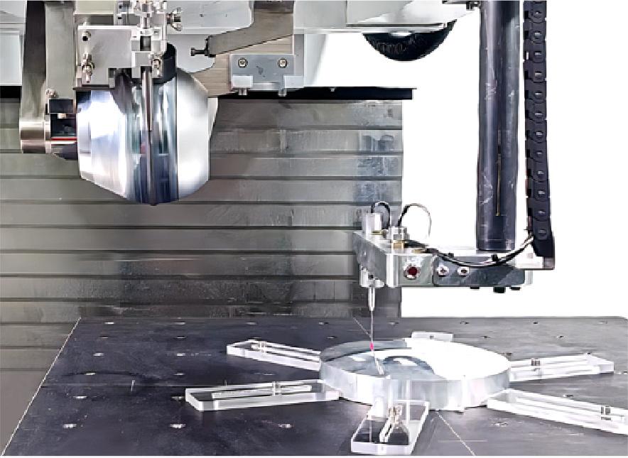
Example of non-contact setup sensing used to capture workpiece position and tilt/orientation before polishing.
01 Large-Format Planar Coverage Nominal maximum planar processing envelope of 700 × 700 mm. | 02 Five Controlled Axes X/Y/Z linear axes and A/B rotary axes; optional C axis by project. |
03 Metrology-Assisted Setup Centering and tilt/orientation sensing supports a repeatable setup route. | 04 Adaptable MRF Tooling Ø150 mm standard wheel; project-adapted configurations within a nominal Ø50–Ø300 mm range. |
Datum definition, secure fixturing, calibration and safety verification remain required. The image does not represent continuous in-process or full-aperture surface metrology.
| Parameter | X | Y | Z |
|---|---|---|---|
Nominal axis travel | ≥1,200 mm | ≥700 mm | ≥450 mm |
Bidirectional accuracy of positioning over full travel* | ≤15 µm | ≤15 µm | ≤12 µm |
Bidirectional repeatability of positioning over full travel* | ≤10 µm | ≤10 µm | ≤8 µm |
Maximum rapid-traverse / axis speed* | 5 m/min | 5 m/min | 5 m/min |
| Parameter | A | B | Optional C axis |
|---|---|---|---|
Angular travel / rotation | −30° to +30° | −30° to +30° | Project-specific |
Bidirectional accuracy of positioning over full travel* | ≤12 arcsec | ≤12 arcsec | Project-specific |
Bidirectional repeatability of positioning over full travel* | ≤8 arcsec | ≤8 arcsec | Project-specific |
Maximum axis speed* | 10 r/min | 10 r/min | Project-specific |
| Item | Reference value / configuratio |
|---|---|
Machine structure | Vertical magnetorheological finishing platform |
Standard controlled axes | X/Y/Z linear axes and A/B rotary axes |
Maximum planar processing envelope | 700 × 700 mm |
Standard MRF wheel diameter | Ø150 mm |
Project-adapted MRF configurations | Nominal Ø50–Ø300 mm head/wheel range, subject to compatibility, calibration, geometry and collision review |
Optional motion | C axis; complete performance and limits defined in the technical proposal |
SPECIFICATION NOTE *Positioning values apply to individual axes over full travel under the agreed test conditions. They do not define multi-axis path accuracy, volumetric accuracy or achievable optical-surface performance. |
MODULE 4 | APPLICATIONS
The PKC700-Q is designed for deterministic correction and final finishing of precision optical surfaces within the evaluated machine, fixture and process envelope.
FLATS | SPHERES | ASPHERES | FREEFORMS |
Space & Astronomical Optics Lenses, mirrors and research optics requiring controlled corrective finishing. | Laser-System Optics Subject to application-specific surface-integrity, contamination and laser-damage validation. |
Imaging Optics Wide-field and other complex-surface imaging components. | Precision Optical Manufacturing Process development, prototypes, custom production and repeat manufacturing. |
| Review input | Configuration impact |
|---|---|
Geometry and clear aperture | Surface access, tool orientation and collision clearance |
Workpiece mass and fixture datum | Support, loading route and available motion envelope |
MRF tool configuration | Local-curvature access, removal-function size and throughput |
Initial/target condition and metrology | Correction strategy and compatible validation route |
MODULE 5 | PERFORMANCE QUALIFICATION
Achievable material-removal rate, surface figure, surface texture and long-duration stability depend on the complete workpiece, process and metrology definition.
| Definition area | Information to confirm |
|---|---|
Workpiece | Substrate and coating, form, overall size, clear aperture, mass and fixture datum |
Initial and target condition | Surface figure, surface texture, removed terms, masks and spatial-frequency range |
MRF process configuration | Head/wheel, MR-fluid state, working gap, calibration state and correction strategy |
Metrology | Instrument, configuration, wavelength, filtering, evaluation scale and uncertainty |
Acceptance | Metric, units, decision rule, repeat measurement, witness and records |
01 Define Workpiece Geometry, incoming condition and metrology operator | 02 Select Configuration Machine, fixture, MRF tool and setup sensing | 03 Agree Validation Sample, FAT/SAT method and decision rules | 04 Retain Records Traceable measurement and process evidence |
TESTING REFERENCES Where applicable, axis tests can be defined with ISO 230-2, optical-surface specifications with ISO 10110 terminology, and surface-texture parameters with the ISO 21920 or ISO 25178 families. These are reference frameworks, not certification claims. |
What is the maximum processing range? |
The maximum planar processing envelope is 700 × 700 mm. Curved-optic capacity also depends on geometry, mass, fixture, sensor access, MRF tool and collision clearance. |
Is the C axis standard? |
No. Rotation mode, positioning performance, speed, load, limits and cable or fluid-line constraints are project-specific. |
What does the integrated non-contact system measure? |
It supports centering and tilt/orientation setup; it is not presented as continuous in-process or full-aperture surface metrology. |
Which MRF wheel sizes are available? |
Ø150 mm is standard. Project-adapted configurations within the nominal Ø50–Ø300 mm range require compatibility, calibration, geometry and collision review. |
How is process performance qualified? |
A defined test piece and agreed metrology plan specify material, form, aperture, conditions, filtering, instrument, uncertainty, process configuration and decision rule. |
PROJECT BASIS Feasibility and acceptance are confirmed against the selected machine configuration, complete optic definition and agreed validation method. |
MODULE 6 | CALL TO ACTION
Share the part, performance and metrology inputs below so the MRF tool, axis access, fixture, clearance and validation route can be assessed together.
WHAT TO SUBMIT • 2D drawing and/or 3D CAD model • Substrate, coating, dimensions, aperture and mass • Fixture interface and datum strategy • Surface form, radius/aspheric definition, sag and slope • Initial and target figure/texture definitions • Error map, instrument, wavelength and data format • Batch, throughput and required options | WHAT THE REVIEW PROVIDES • Initial geometry and process-feasibility assessment • Recommended axis and MRF tool configuration • Fixture and metrology-route boundaries • Reachability and collision-review requirements • Proposed validation and acceptance route • Inputs required for a project quotation |
PRIMARY CTA Request a Configuration Review |
Secondary actions: Submit Workpiece Data • Talk to an Application Engineer
Project-specific targets are confirmed in the technical proposal and agreed validation plan.


