


| Quantity: | |
|---|---|


Deterministic finishing for flat, spherical, aspheric and freeform optics within a 500 × 500 mm maximum planar processing envelope
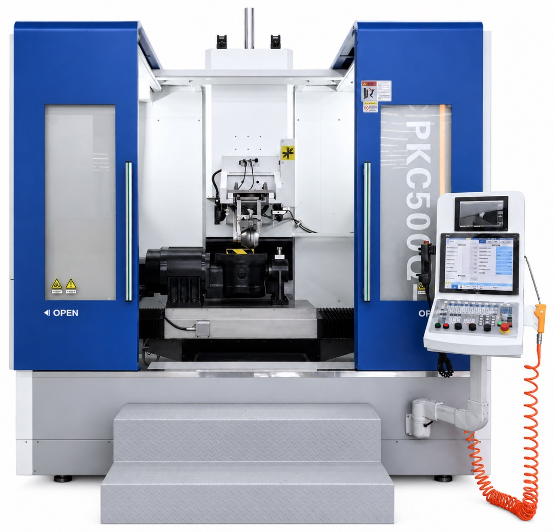
PKC500-Q multi-axis magnetorheological finishing machine.
At a glance: Six mechanical axes (X/Y/Z/A/B/C) | 500 × 500 mm maximum planar processing envelope | Standard Ø50 mm MRF head | Ø150 mm option | Typical surface figure capability ≤4.2 nm RMS under defined conditions.
SECTION 1 | PAIN-POINT INTRODUCTION
Medium-aperture aspheres and freeforms require more than sufficient machine travel. Manufacturers must maintain tool access as local surface normals change, keep the removal function predictable through extended correction cycles, and convert metrology results into reliable dwell-time and tool-path commands. Aperture, sag, radius, fixture height, wheel diameter and the collision envelope must be evaluated together. When these variables are not matched, the result can be repeated setup, inconsistent correction efficiency, longer cycle time and uncertainty about reaching the target figure and roughness.
The practical selection question: not only whether the part fits, but whether the machine can reach the required surface orientations with an appropriate removal-function footprint and a verified closed-loop process.
SECTION 2 | SOLUTION
The PKC500-Q is designed for deterministic correction of flat, spherical, aspheric and freeform optical surfaces in the medium-aperture class. Its vertical machine configuration combines X/Y/Z linear axes and A/B/C mechanical rotary axes with virtual-axis-assisted process strategies, an integrated magnetorheological finishing system, dedicated control and process-metrology functions, and finishing-process software.
Process parameters, metrology data and machine workflows are managed within one platform. The standard Ø50 mm MRF head and optional Ø150 mm head allow the process configuration to be selected around curvature access, removal-function footprint and throughput requirements. Other head sizes require machine-interface, workspace and process qualification before they can be proposed for a project.
Standard platform scope: Vertical machine structure; X/Y/Z linear axes and A/B/C rotary axes; standard Ø50 mm MRF head; circulation system and process software; dedicated control and non-contact process-metrology functions; centralized management of process parameters, removal functions, trajectories and workflows.
1. Application assessment. Provide the optic drawing, substrate, incoming surface-figure data, target figure and roughness, and throughput requirement so that the wheel, fixture and process route can be evaluated.
2. Setup and calibration. Load the optic; calibrate coordinates, workpiece pose, wheel, working gap and touch-off. Use non-contact process metrology when required to assist pose verification.
3. Removal-function characterization and planning. Characterize the ribbon/removal function for the installed wheel and MRF fluid, import metrology data, and calculate the dwell-time solution and tool path.
4. Simulation and automatic execution. Complete program simulation and collision checks before automatic finishing, then monitor temperature, flow, wheel speed and other critical process parameters.
5. Verification and process closure. Re-measure the optic and repeat the correction loop as required. Re-characterize the removal function whenever the wheel size or MRF fluid changes.
SECTION 3 | CORE ADVANTAGES
The platform is built around the relationship between part geometry, tool access, removal-function stability and a controlled metrology-to-correction workflow.
1. Six Mechanical Axes with Virtual-Axis Process Strategies
X/Y/Z linear axes and A/B/C mechanical rotary axes support complex workpiece orientations, while virtual-axis-assisted strategies extend process-planning flexibility. Actual steep-slope capability remains dependent on the optic geometry, fixture, trajectory, axis envelope and selected wheel.
2. Wheel Selection Matched to Geometry and Throughput
A standard Ø50 mm head and optional Ø150 mm head allow the removal-function footprint to be matched to curvature accessibility and productivity objectives. Other head sizes shown in the source platform data are not established PKC500-Q configurations and require project-specific mechanical and process qualification.
3. Condition-Bound Removal-Function Stability
Under the defined source test setup, removal-function variation remains below 4% during a six-hour continuous run. For contractual use, the wheel, MRF fluid, substrate, temperature, flow, wheel speed, working gap, sampling method and variation definition must be specified.
4. Automated Process Workflow
Ribbon characterization, calibration, touch-off, parameter management, path generation and automatic execution are integrated to reduce manual setup steps and support consistent process execution.
5. Metrology-Assisted Setup and Program Verification
Non-contact process-metrology functions can assist workpiece geometry and pose identification, curved-surface program verification and error analysis. The exact metrology configuration and system boundary should be confirmed for the selected machine package.
6. Integrated Control Platform
The integrated CNC, process software and core functional modules support centralized process management, maintainability and software evolution. Exact software functions and component brands are defined by the contracted configuration.
Category | Parameter | Source Value |
System | Machine configuration | Vertical machine configuration |
System | Mechanical axes | X/Y/Z linear axes; A/B/C rotary axes |
System | Process strategy | Virtual-axis-assisted process capability; application dependent |
Travel / rotation | X/Y/Z effective travel | X ≥ 800 mm; Y ≥ 600 mm; Z ≥ 400 mm |
Travel / rotation | A/B/C rotation | A: -30° to +30°; B: -30° to +30°; C: 0° to 360° |
Motion | Bidirectional positioning accuracy, full travel | X/Y ≤ 15 µm; Z ≤ 12 µm; A/B ≤ 12 arcsec; C ≤ 15 arcsec |
Motion | Bidirectional positioning repeatability, full travel | X/Y ≤ 10 µm; Z ≤ 8 µm; A/B ≤ 8 arcsec; C ≤ 10 arcsec |
Motion | Maximum axis speed | X/Y/Z: 5 m/min; A/B: 10 rpm; C: 100 rpm |
Motion | Maximum X-axis acceleration | 0.15 g; other-axis values not published |
Geometry | Linear-axis straightness | X: 12 µm/800 mm; Y: 10 µm/600 mm; Z: 10 µm/400 mm |
Processing | Maximum planar processing envelope | 500 × 500 mm |
Processing | Finishing-head configuration | Standard Ø50 mm; optional Ø150 mm; other sizes require engineering qualification |
Typical process data | Volumetric removal rate on fused silica | 0.03-0.15 mm³/min with Ø50/Ø150 mm heads |
Typical result | Surface-figure error | ≤ 4.2 nm RMS (equivalent to λ/150 at 632.8 nm) |
Typical result | Surface roughness | Ra ≤ 0.5 nm |
Typical stability | Removal-function variation | < 4% during a six-hour continuous run under a defined test setup |
Performance note. Typical results are not unconditional guarantees and are not necessarily simultaneous. Actual performance depends on the optic and substrate, incoming error spectrum, clear aperture/evaluation area, wheel and MRF fluid, wheel speed, working gap, temperature, flow, metrology, filtering/data processing and correction strategy. Final configuration, test method and acceptance limits are defined in the agreed technical specification.
SECTION 4 | APPLICATIONS
The machine is intended for medium-aperture optical manufacturing programs that need deterministic correction across multiple surface forms while balancing curvature access, process footprint and throughput.
Flat, spherical, aspheric and freeform optical surfaces.
Up to the 500 mm class within a maximum planar processing envelope of 500 × 500 mm. Curved-part feasibility must additionally consider aperture, thickness, mass, radius, sag, fixture and collision envelope.
Medium-aperture transmissive and reflective optics for high-power lasers, precision imaging, space optics and advanced metrology.
Process development, prototype qualification, custom production and multi-product manufacturing, with wheel selection optimized around geometry and cycle-time requirements.
Wheel-selection principle: Select Ø50 or Ø150 mm from the 3D part model, required local curvature access, target removal-function footprint and throughput. Any other head size requires PKC500-Q interface, workspace and process qualification before quotation.
Steep-slope capability: In a qualified physical-/virtual-axis configuration, local surface-normal coverage can reach approximately 60°. This is not the travel of a single tilt axis: A/B mechanical travel remains ±30°, and each project requires reachability and collision verification.
SECTION 5 | TRUST AND VERIFICATION
For ultra-precision equipment, credibility comes from linking each published value to a defined configuration, workpiece, measurement method and acceptance rule. The PKC500-Q page therefore distinguishes machine capacity from application feasibility, and typical process results from contractual guarantees.
Verification Item | What Should Be Defined Before Order |
Geometry feasibility | Review the 2D drawing and 3D model against the fixture, selected wheel, axis travel and collision envelope. |
Process feasibility | Define substrate, incoming figure, target figure/roughness, throughput, MRF head, fluid and intended correction strategy. |
Typical performance | Record the test optic, clear aperture/evaluation area, incoming condition, environment, metrology, filtering/data processing and cycle conditions. |
Machine acceptance | State the final configuration, test standard/method, compensation status, measurement uncertainty and acceptance limits in the agreed technical specification. |
The source datasheet includes the following published process records. They demonstrate completed correction work, but they are not universal machine guarantees because the public record does not include every material, aperture, metrology and data-processing condition.
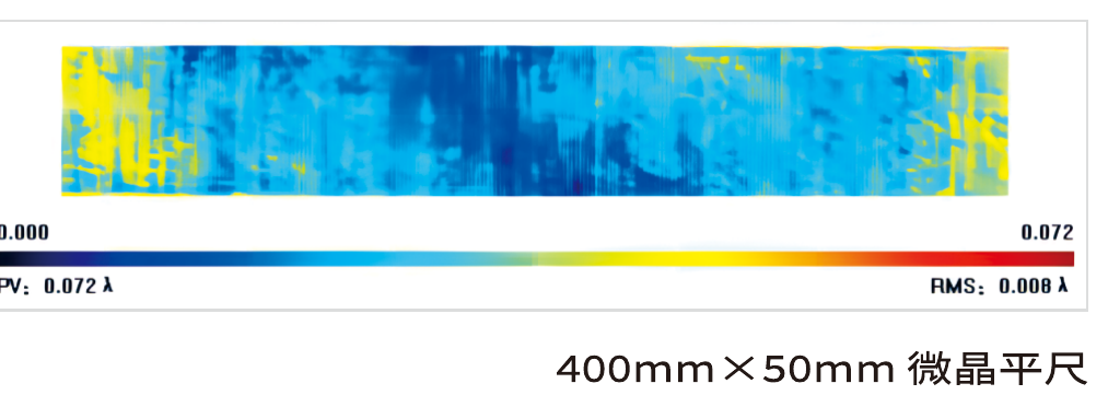
Representative record — 400 × 50 mm glass-ceramic straightedge: PV 0.072 λ; RMS 0.008 λ. The source does not state the reference wavelength, so these values must remain in λ units.
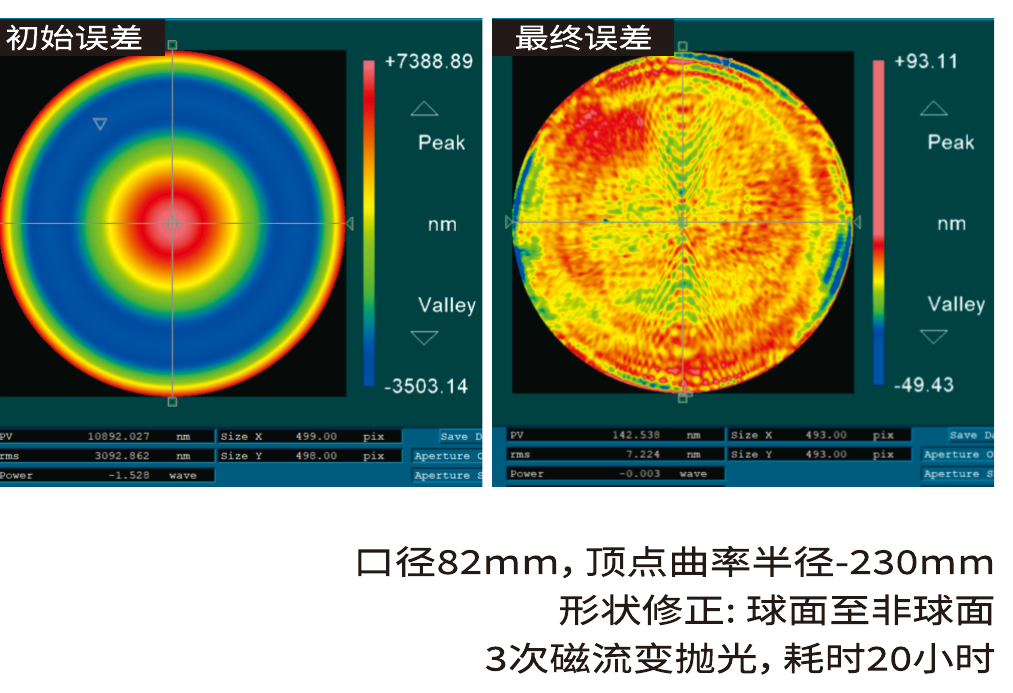
Representative record — Ø82 mm asphere, vertex radius R = −230 mm: spherical-to-aspheric correction in three MRF cycles, approximately 20 h total. Initial PV/RMS ≈ 10.992/3.093 µm; final PV/RMS ≈ 142.538/7.224 nm.
Case-data boundary. The public record does not provide the complete material specification, effective aperture, instrument chain, filtering/removal rules, MRF head and fluid, measurement uncertainty or report number. Treat these as representative records, not guarantees for all optics.
1. What workpiece size is suitable for the PKC500-Q?
The maximum planar processing envelope is 500 × 500 mm. For curved optics, actual aperture, thickness, mass, radius and sag must also be checked against the fixture, wheel, axis travel and collision envelope.
2. Why is the material-removal-rate range so broad?
Removal rate varies with head diameter, MRF fluid, wheel speed, working gap, substrate and the required removal-function shape. The published 0.03-0.15 mm³/min range applies to fused silica with the commonly used Ø50/Ø150 mm heads under condition-dependent process settings.
3. Can the machine finish steep freeform surfaces?
In a qualified physical-/virtual-axis configuration, local surface-normal coverage can reach approximately 60°. A/B mechanical travel remains ±30°, and the actual limit must be verified from the 3D model, tool path, fixture, head and collision envelope.
4. Under what conditions does the six-hour variation below 4% apply?
It is a typical stability result under a defined test setup. The wheel, MRF fluid, substrate, temperature, flow, wheel speed, working gap, measurement method, sampling interval and statistical definition must be specified for contractual use.
5. Can wheel modules be changed quickly?
The machine supports modular Ø50/Ø150 mm head changeover. The source records about 20 minutes for change and reset under a qualified setup; cleaning, circulation conditions and removal-function recalibration can extend the total process-change time.
SECTION 6 | CALL TO ACTION
To determine whether the PKC500-Q is the right platform, submit the optic and process data rather than only a nominal part diameter. The information below enables an application-specific review of geometry access, wheel configuration, fixture concept, process route and acceptance targets.
Information to Provide
Part definition. 2D drawing and, where available, a 3D model; external dimensions, mass and locating datum; surface form, curvature or aspheric equation; effective aperture; thickness; sag and maximum local surface-normal angle.
Material and condition. Substrate, coating status if applicable, upstream process and current surface condition.
Incoming metrology. Initial PV/RMS and surface-texture data; instrument, wavelength, effective aperture or mask, stitching method, removed terms, filtering and data format.
Target specification. Required PV/RMS and texture, evaluation method, acceptance criteria and acceptable number of correction cycles.
Production objective. Upstream process, target cycle time, annual or batch volume, prototype or production use, and product-mix requirements.
Required configuration. Preferred MRF head and fluid, rotary-axis use, fixture concept, metrology options and any required system-integration boundary.
Request Application Evaluation
Submit Your Workpiece
Discuss Machine Configuration


