


| Quantity: | |
|---|---|


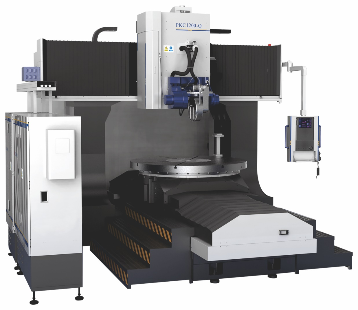
Representative product image of the PKC1200-Q gantry-type MRF platform. Visible hardware and appearance may vary with project configuration.
Nominal XY envelope | Linear travel | Standard axes | Standard MRF finishing head |
1,200 × 1,200 mm | X 1,500 / Y 1,300 / Z 550 mm | X / Y / Z / A / B | Ø300 mm |
Workpiece feasibility The 1,200 × 1,200 mm value is a nominal XY processing envelope, not a universal maximum workpiece size. Usable envelope is confirmed for each optic and configuration based on geometry, mass, support, fixture, finishing-head access, axis reach and collision clearance.
Scaling optical finishing to the 1,200 mm class is not only a question of aperture. Workpiece mass, curvature or sag, support, gravitational state, thermal stability, fixture geometry, tool access and metrology must be assessed together.
The engineering objective is a controlled correction workflow with defined setup, calibrated removal, verified tool paths and repeatable measurement conditions—not simply a larger polishing envelope.
The PKC1200-Q combines a gantry structure, X/Y/Z linear axes, A and B rotary axes, an MRF fluid-circulation system, process software, primary and auxiliary workstations, and standard on-machine non-contact measurement coordinated with machine motion.
Automated or one-touch routines support ribbon characterization, removal-function calibration and tool setting. Surface-data processing, dwell-time calculation, tool-path generation and program execution complete the workflow.
1 | 2 | 3 | 4 | 5 | 6 |
Measure | Process data | Calibrate removal function | Solve dwell time | Polish | Re-measure |
Measurement boundary Surface-form acquisition and final re-measurement use the agreed metrology method. Part-specific large-aperture surface-form metrology and stitching solutions are project-configured.
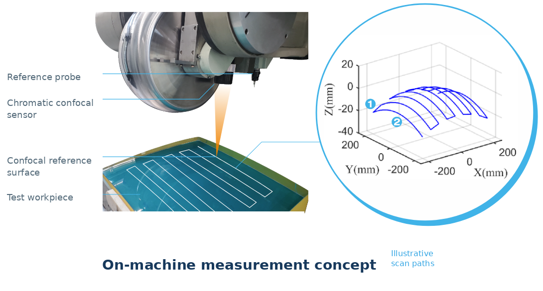
Source schematic illustrating one measurement arrangement and example scan paths. Sensor make/model, range and accuracy are not defined here; part-specific large-aperture surface-form metrology is project-configured.
Configuration boundary The schematic is an arrangement example, not a standard bill of materials or a full-aperture acceptance-metrology specification. Standard on-machine non-contact measurement supports workpiece-pose identification, program verification and error analysis.
| Standard configuration | Project-configured options |
Gantry structure; X/Y/Z linear axes; A/B rotary axes; Ø300 mm MRF finishing head; fluid-circulation system; process software | Multi-turn C axis; project-adapted Ø50–300 mm MRF head/wheel configurations |
Primary and auxiliary workstations; on-machine non-contact measurement coordinated with machine motion for pose identification, program verification and error analysis | Dedicated support and fixtures; application-specific process packages; large-aperture surface-form metrology and stitching solutions |
Option boundary Project-adapted Ø50–300 mm head/wheel configurations are subject to engineering selection, reconfiguration, recalibration and collision-clearance review. The multi-turn C axis is not standard.
1. Define the workpiece - Submit the optic geometry, substrate, mass, clear aperture, incoming condition and target specification.
2. Complete engineering review - Define support, fixture, finishing-head/wheel configuration, fluid system, optional rotary axis and metrology plan.
3. Load and calibrate - Secure the optic and run the configured tool-setting, ribbon-characterization and removal-function-calibration routines.
4. Generate the correction program - Acquire the incoming figure map using the agreed metrology method, import the data, calculate dwell time and generate the tool path.
5. Execute and verify - Verify the program, execute MRF correction, re-measure and iterate to the agreed endpoint.
Large working volume — X/Y/Z travels of 1,500 mm, 1,300 mm and 550 mm support a published nominal XY processing envelope of 1,200 × 1,200 mm.
Standard five-axis architecture — X/Y/Z/A/B motion supports large workpieces and complex surface orientations; a multi-turn C axis is available as a project option.
Structured MRF workflow — Ribbon characterization, removal-function calibration, tool setting, dwell-time calculation and tool-path execution form one defined process sequence.
Measurement-assisted setup — Where included and validated in the project configuration, measured workpiece-pose data may be used for coordinate or tool-path compensation, reducing reliance on repeated manual leveling.
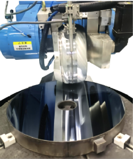
Source image illustrating a curved-workpiece setup beneath a finishing head. Setup image only; no surface-performance value or link to the representative figure-map record should be inferred.
Configurable finishing footprint — A Ø300 mm MRF finishing head is standard. Project-adapted Ø50–300 mm head/wheel configurations are selected for curvature, accessibility and process requirements, then reconfigured and recalibrated for the application.
How to read these values Published machine specifications describe the platform. Representative results apply only to the stated source record. Project commitments are defined in the signed technical agreement and verified using the agreed acceptance procedure.
Parameter | X | Y | Z |
Travel | 1,500 mm | 1,300 mm | 550 mm |
Published positioning accuracy* | ≤16 µm | ≤16 µm | ≤12 µm |
Published positioning repeatability* | ≤10 µm | ≤10 µm | ≤8 µm |
Published maximum speed* | 5 m/min | 5 m/min | 3 m/min |
Parameter | A | B | Optional C |
Travel | −30° to +30° | −30° to +30° | Project-specific multi-turn rotation |
Published positioning accuracy* | ≤12 arcsec | ≤12 arcsec | Defined in the technical agreement |
Published positioning repeatability* | ≤8 arcsec | ≤8 arcsec | Defined in the technical agreement |
Published maximum speed* | 10 r/min | 10 r/min | Defined in the technical agreement |
Specification note *Source-documented published axis values. For contractual acceptance, test locations, directionality, number of cycles, compensation state, environmental conditions, measurement uncertainty and reporting rules shall be defined in the signed technical agreement and agreed FAT procedure; SAT applies only where contractually included. Machine-axis positioning performance is not equivalent to final optical surface accuracy.
Processing Capacity and Qualification
Item | Public value or scope | Qualification boundary |
Nominal XY processing envelope | 1,200 × 1,200 mm | Usable envelope is workpiece- and configuration-specific |
MRF head/wheel configuration | Ø300 mm MRF finishing head standard | Project-adapted Ø50–300 mm configurations require reconfiguration, recalibration and clearance review |
Removal rate | Established through application qualification | Depends on substrate, head/wheel configuration, fluid system, working gap and process parameters |
Surface-form / texture acceptance | Defined for the agreed test optic and project-specified Ra/Rq or Sa/Sq metric | Requires a clear aperture, support state, metrology and data-processing method, substrate, sampling, filtering, instrument and uncertainty |
Suitable applications include final figure correction of large flat, spherical, aspheric and freeform optics for astronomy, aerospace, laser and infrared systems. Each project remains subject to workpiece, support, process and metrology review.
Application field | Typical component | Surface form | Engineering focus |
Astronomy | Large mirrors and lenses | Flat, spherical, aspheric, freeform | Support, gravitational state and large-aperture metrology |
Aerospace | Large aerospace optical components | Spherical, aspheric, freeform or complex | Material, fixture, workpiece pose and project qualification |
Laser optics | Large laser optical components | Flat, spherical or aspheric | Material, surface condition and process-specific qualification |
Infrared optics | Large infrared optical components | Spherical, aspheric or freeform | Substrate compatibility, support and measurement method |
Custom engineering | Large optics requiring pose measurement or compensation | Multiple forms | Head access, optional rotary axis, fixture and collision clearance |
Selection boundary A nominal diameter or rectangular size alone is not sufficient to establish process feasibility. Submit the complete optic geometry and fixture constraints for review.
Representative Figure-Map Record — Reported Size X/Y: 482.0 mm
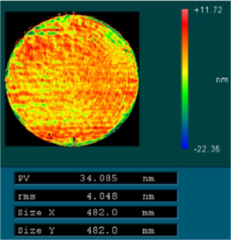
Source figure-map record showing Size X = 482.0 mm, Size Y = 482.0 mm, PV = 34.085 nm and RMS = 4.048 nm.
Reported Size X / Size Y | Reported PV | Reported RMS |
482.0 mm / 482.0 mm | 34.085 nm | 4.048 nm |
Result boundary This case-specific record is not a 1,200 mm full-aperture guarantee. The available record does not state substrate, exact surface form, clear-aperture relationship, initial figure, instrument or wavelength, removed terms, filtering, processing time or measurement uncertainty.
Engineering feasibility review — Geometry, mass, support, fixture, finishing-head access, axis reach and collision clearance are assessed before the configuration is finalized.
Defined project scope — Standard equipment, project options, metrology interfaces, fixtures, accessories and delivery responsibilities are listed in the signed technical specification.
Defined acceptance basis — The test optic, substrate, clear aperture, support state, instrument, wavelength, removed terms, filtering, uncertainty and conformity decision rule are agreed before acceptance.
Documented acceptance — Any contractual commitments are defined in the signed technical agreement and verified through the agreed FAT and, where contractually included, SAT procedures. Results are documented in the corresponding acceptance records. Metrological traceability is stated only where valid calibration evidence is available.
• Test optic, substrate, geometry, mass and clear aperture
• Incoming and target figure or surface-texture requirements
• Support condition, gravitational orientation and thermal state
• Instrument, wavelength, filtering, data processing and measurement uncertainty
• Agreed FAT and, where included, SAT procedure and conformity decision rule
Not necessarily. Feasibility also depends on thickness, mass, curvature or sag, support, fixture, finishing-head/wheel configuration, axis reach and collision clearance.
No. X/Y/Z/A/B are standard. The multi-turn C axis is project-configured; total angular travel, speed, positioning performance, load capacity, limits and cable or hose management are defined in the technical agreement.
No. Standard on-machine non-contact measurement supports pose identification, program verification and error analysis. Final acceptance requires a measurement method appropriate to the optic, clear aperture and agreed specification.
No. Contractual limits apply only when the test optic, process conditions, metrology method and acceptance rules are defined in the signed technical agreement and agreed FAT and, where applicable, SAT procedures.
Submit the minimum workpiece data below so the engineering team can review processing reach, support, fixture, finishing-head/wheel selection, optional-axis requirements, metrology strategy and project-specific acceptance criteria.
• Drawing or complete 3D model
• Substrate, overall dimensions, thickness and mass
• Surface form, radius or sag and clear aperture
• Mounting datum and support or loading constraints
• Incoming surface condition and figure map, if available
• Target surface-figure and surface-texture requirements
• Measurement instrument, wavelength, data format and report
• Fixture concept, optional-axis or installation constraints
• Expected quantity, schedule or cycle-time objective
REQUEST A FEASIBILITY REVIEW Submit your optic geometry and target specification.
REQUEST A TECHNICAL QUOTATION Include the required configuration, delivery and acceptance scope.
Next step Submit your optic geometry and target specification for a feasibility review and project-specific configuration proposal.


