


| Quantity: | |
|---|---|


DETERMINISTIC PRECISION-OPTICS FINISHING
Deterministic corrective finishing for flat, spherical, aspheric and freeform precision optics
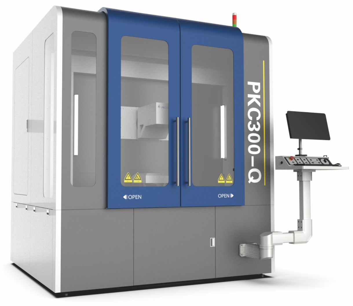
The PKC300-Q combines X/Y/Z linear axes with B/C rotary axes, a granite base, a bottom-mounted finishing head and inverted-workpiece processing. Dedicated machine-control and process software supports removal-function characterization, dwell-time calculation and metrology-feedback correction within a nominal 300 × 300 mm XY processing envelope, subject to workpiece-specific feasibility review.
300 × 300 mm Nominal XY envelope | X/Y/Z/B/C Five machine axes | Ø50 mm Standard finishing wheel | ≤4.2 nm RMS* Typical figure metric |
Start your project: Request a Workpiece Feasibility Review
01 | THE CHALLENGE
When conventional polishing approaches the final figure target, the remaining error becomes a geometry-and-data problem. Complex slopes, changing local normals and small correction depths demand controlled removal based on the measured surface error. Repeat production also requires a consistent setup and calibration sequence as workpieces, wheels and process configurations change.
• Correct residual figure error without removing unnecessary material across the full surface.
• Reach convex, concave and edge regions while maintaining clearance among the optic, workholding and finishing head.
• Connect process calibration, measured error data and remeasurement in a repeatable correction workflow.
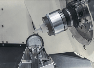
Inverted finishing access for a high-slope curved surface.
02 | THE PROCESS
A five-stage MRF workflow connects workpiece evaluation, removal-function calibration and iterative correction.
1. Review the workpiece: Evaluate the drawing or 3D model, dimensions, clear aperture, material, incoming figure and target specification.
2. Configure and calibrate: Select the workholding, finishing wheel and MRF-fluid system; establish the work coordinate, working gap and touch-off position.
3. Characterize the process: Set the MRF ribbon condition and characterize the removal function for the selected wheel, fluid and workpiece configuration.
4. Calculate and finish: Import measured surface-error data, calculate dwell time and tool path, verify clearance, and execute the finishing cycle.
5. Remeasure and iterate: Use the project-defined external metrology process to verify the result and run additional correction cycles when required.
Metrology interface: Surface-metrology hardware, measurement method and data-interface scope are defined for each project.
03 | CORE ADVANTAGES
| High-Slope Access | Standard Ø50 mm Head | Project-Configured Ø150 mm |
|---|---|---|
|
|
|
Inverted finishing access for a high-slope curved surface. | Standard finishing-head configuration for routine MRF correction. | Larger head assembly available after project-specific configuration review. |
01 Five-axis geometry control. X/Y/Z linear axes and B/C rotary axes orient flat, spherical, aspheric and freeform surfaces, subject to workpiece-specific 3D feasibility review.
02 Compact finishing architecture. A granite base, enclosed processing area, bottom-mounted finishing head and inverted-workpiece layout organize the precision-finishing zone.
03 Guided process software. Step-based routines support ribbon characterization, calibration, touch-off, parameter recall, dwell-time calculation and tool-path execution.
04 Efficient workpiece handling. A quick-loading/clamping device supports controlled changeovers and repeat-production workflows.
05 Configurable MRF process system. A Ø50 mm finishing wheel and one mobile independent circulation unit are standard; larger head/wheel assemblies and additional units are project-configured.
Configuration principle: Wheel, fluid, workholding and software scope are selected against the optic geometry, substrate, target result and production route.
PKC300-Q | ENGINEERING DATA
Machine and motion
Parameter | Specification |
Machine configuration | Granite base; fully enclosed processing area; bottom-mounted finishing head; inverted-workpiece processing |
Axis configuration | Five machine axes: X/Y/Z linear axes and B/C rotary axes |
Axis travel / range | X ≥650 mm; Y ≥350 mm; Z ≥420 mm; B: ±180°; C: continuous rotation |
Positioning accuracy | X/Y/Z ≤12 µm; B/C ≤12 arcsec |
Positioning repeatability | X/Y/Z ≤8 µm; B/C ≤8 arcsec |
Maximum axis speed | X/Y/Z: 5 m/min; B: 12 rpm; C: 100 rpm* |
Nominal XY processing envelope | 300 × 300 mm** |
* Actual C-axis safe speed depends on workpiece mass, eccentricity, workholding, dynamic balance and the project safety review. ** Usable aperture depends on surface geometry, sag, local normal angle, workholding, wheel size and collision envelope. Axis accuracy and repeatability use the terminology of the current machine data; the applicable test direction, cycle count, compensation state, load, environment, instrumentation and measurement uncertainty are defined in the project technical specification.
PKC300-Q | PROCESS DATA
MRF Process System
| Parameter | Specification |
|---|---|
Finishing-wheel configuration | Standard Ø50 mm; project-configured head/wheel assemblies within Ø50–150 mm |
MRF-fluid circulation | One mobile independent circulation unit in the standard scope; additional units available by project |
Typical volumetric removal rate | 0.05–0.15 mm³/min† |
Typical residual figure-error metric | RMS ≤λ/150 at λ = 632.8 nm (approximately 4.2 nm RMS)† |
Typical profile roughness | Ra ≤0.5 nm† |
Recorded local surface-normal reach | Approximately 90° for convex and 60° for concave geometries† |
† Process-performance values are typical rather than universal. Actual results depend on substrate, geometry, initial condition, evaluated aperture, wheel and fluid configuration, process settings, fitted reference, removed terms, filtering, instrument and measurement method.
04 | APPLICATIONS
Designed for deterministic correction of small- to medium-aperture precision optics within a workpiece-qualified process envelope.
| Application dimension | Typical fit |
|---|---|
Surface forms | Flat, spherical, aspheric and freeform optical surfaces |
Optic types | Precision lenses, mirrors and other complex optical surfaces requiring figure correction |
Target fields | Precision imaging, laser optics, infrared optics, optical metrology components and process development |
Production modes | R&D, process qualification, prototypes, high-mix low-volume manufacturing and repeat batches |
Material classes | Optical glass, fused silica and other compatible substrates after material- and fluid-specific process validation |
A strong fit when
• The optic passes geometry, workholding and collision review within the nominal XY processing envelope.
• Measured figure-error data are available for deterministic dwell-time correction.
• The product mix benefits from guided setup, parameter recall and repeat correction workflows.
• The selected substrate, finishing wheel and MRF-fluid system can be qualified against the target result.
Workpiece-specific evaluation: Submit the optic drawing or CAD model to assess radius, sag, clear aperture, local surface-normal angle, workholding and collision envelope in 3D.
05 | TRUST & PROOF
A representative process photograph shows the inverted-workpiece layout on a recorded spherical-optic job.
This representative setup illustrates how a spherical workpiece is positioned above the bottom-mounted MRF finishing head. The recorded optic had a nominal diameter of Ø170 mm and a spherical radius of R = 158 mm. The photograph documents the physical processing arrangement; workpiece-specific parameters and acceptance targets are established through the project feasibility and qualification process.
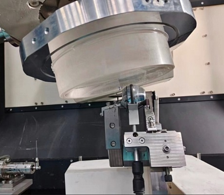
Representative spherical-workpiece setup: Ø170 mm nominal diameter and R = 158 mm.
| Case element | Recorded configuration |
|---|---|
Surface form | Spherical optical surface |
Nominal workpiece diameter | Ø170 mm |
Spherical radius | R = 158 mm |
Processing layout | Inverted workpiece above the bottom-mounted MRF finishing head |
Case boundary: Representative setup only. Actual results depend on the evaluated aperture, substrate, incoming condition, wheel/fluid configuration, process settings and the agreed measurement method.
PKC300-Q | PROJECT ASSURANCE
Published machine and process values are interpreted against the actual optic and measurement definition. The project review connects geometry, substrate, workholding, wheel and fluid configuration, process settings, surface-error data and target criteria before the machine configuration and acceptance route are finalized.
• A preliminary 3D feasibility and collision assessment for the workpiece and workholding.
• A recommended finishing-wheel, circulation-unit and process configuration.
• A measurement-data workflow and project-specific acceptance definition.
• A sample-processing or production qualification route when required.
Performance definition: Project-specific guarantees and acceptance methods are established in the agreed technical specification.
What surfaces and workpiece geometries can be processed?
The PKC300-Q supports flat, spherical, aspheric and freeform surfaces. Feasible aperture, radius, sag, local surface-normal angle, workpiece mass and workholding are evaluated from the drawing and 3D collision envelope.
How is usable aperture and steep-angle capability evaluated?
The nominal XY envelope is 300 × 300 mm. Recorded local surface-normal reach is approximately 90° for convex and 60° for concave geometries under qualified conditions. Actual reach and usable aperture require workpiece-specific 3D feasibility and collision review.
Is optical metrology included in the standard configuration?
Measured surface-error data are used for dwell-time calculation and iterative correction. Surface-metrology hardware, measurement method and data-interface scope are defined for each project.
Which finishing-wheel and MRF-fluid configurations are available?
A Ø50 mm finishing wheel and one mobile independent circulation unit are standard. Project-configured head/wheel assemblies within Ø50–150 mm and additional circulation units can be evaluated. Each wheel or fluid-system configuration requires appropriate process characterization.
What performance can be expected for my optic?
The published process values are typical results under defined workpiece, process and metrology conditions. A project review considers the substrate, geometry, incoming error, evaluated aperture, process configuration, data treatment and measurement method before a target is agreed.
Is the PKC300-Q suitable for repeat or batch production?
Quick loading/clamping, guided setup and process-parameter recall support repeat and batch workflows. Actual cycle time and throughput depend on incoming error, required removal, substrate, wheel size, process route and the metrology loop.
06 | NEXT STEP
Share your optic data for a geometry, process and configuration assessment tailored to the workpiece.
Share the material, approximate dimensions, surface geometry, incoming condition and target specification. APEX can review the workpiece against the machine configuration, workholding and measurement requirements. Any sample trial and acceptance conditions are agreed for the project.
Primary action: Submit Your Workpiece Data
| Send | Include |
|---|---|
Drawing or 3D model | Overall dimensions and clear aperture |
Surface definition | Form, radius or sag, and critical local geometry |
Material | Substrate and coating status |
Surface quality | Incoming and target figure/texture; measurement file if available |
Production need | Prototype or batch quantity and expected schedule |
What you receive
• A preliminary geometry, workholding and collision assessment.
• A recommended wheel, circulation-unit and process configuration.
• A proposed sample-processing or quotation pathway for the project.
Available next steps
• Discuss Sample Processing
• Request a Project Quotation
PKC300-Q | Deterministic MRF correction built around your optic and measurement data


