Email: sales@apex-upt.com   |    WhatsApp: +8618115191816

Precision Optics Manufacturing Equipment & Engineering Solutions

Build a project-defined manufacturing capability from a specified blank or preform to an optical component verified against the agreed acceptance items—or, where required, to an aligned optical assembly.
APEX coordinates the route, equipment, tooling, workholding, metrology, interfaces, utilities, validation and delivery scope needed to establish or upgrade precision-optics manufacturing capability. Each solution is configured around the material, geometry, incoming condition, target form and texture, volume, inspection method, coating or assembly requirement and site constraints—not one equipment catalog or process technology.
Home » Solutions

Choose Your Precision Optics Manufacturing Solution

Tell us which optical component you need to manufacture and what it must achieve. APEX coordinates process routes, equipment, tooling, metrology and engineering interfaces for integrated production lines or custom equipment.​​​​​​​
01

Solution 01 | Integrated Production Line Solutions

Build or upgrade manufacturing capability for a defined optical component family. APEX coordinates machining, finishing, metrology and required downstream equipment from the agreed blank or preform to the target delivery state. We align process interfaces, site requirements and supplier responsibilities. Stations are selected for the material, component requirements and production goals, using independent workstations, linked cells or agreed automation as appropriate.

  • Process route and equipment configuration
  • Process interfaces and verification planning
Explore Production Line Solutions
02

Solution 02 | Custom Equipment Solutions

Configure a machine or station for a defined component, critical process or production bottleneck. APEX reviews material compatibility, geometry access, workholding and metrology before selecting a suitable platform. Necessary changes may involve tooling, process modules, software or interfaces. Engineering review defines a feasible configuration, its technical limits and the required verification plan, providing a clear basis for the equipment purchase decision.

  • Platform selection and necessary customization
  • Process review and agreed sample trials
Explore Custom Equipment Solutions

Integrated Production Line Solutions

For a defined optical component family, APEX coordinates equipment and engineering interfaces from the agreed blank or preform to the target delivery state, considering processing, measurement, throughput and site conditions together.
INTEGRATED PRODUCTION LINE

Modular Precision Optics Production Line Workflow

A precision optics manufacturing line can connect blank preparation, primary machining, qualified corrective finishing, metrology and final verification. The actual equipment sequence, transfer method and automation level are defined for the component family, process route and contracted delivery state.

  1. STEP 01

    Incoming Blank Preparation

    Confirm the blank or preform identity, incoming condition, datum strategy and handling requirements before primary processing.

    Identity · Condition · Datums

  2. STEP 02

    Primary Optical Machining

    Select grinding, polishing or ultra-precision diamond machining according to the qualified material, geometry, allowance and target surface.

    Generate the required geometry

  3. OPTIONAL

    Corrective Finishing

    Apply a qualified corrective process, such as magnetorheological finishing, only when the measured residual error and project route require it.

    May be bypassed when unnecessary

  4. STEP 04

    Defined Precision Metrology

    Measure the component in the agreed state, register the data to defined datums and validate the measurement and evaluation method.

    Register · Validate · Evaluate

  5. STEP 05

    Contract-Defined Final Verification

    Verify the specified delivery state using the agreed acceptance items, measurement conditions, decision rules and records.

    Specified State · Decision Rule · Records

Bypass Route

When corrective finishing is not required, the qualified primary machining result can proceed directly to defined metrology and final verification.

Downstream Processing

Where specified, cleaning and conditioning, coating and/or assembly are completed after measurement, followed by remeasurement or final verification as defined.

Measurement-Guided Correction Loop

Measurement data → engineering review → select a qualified correction process → execute correction → re-measure

Functional workflow only — equipment, station sequence, zoning, interfaces and automation are defined for each project.

  • 01 | When it fits
    More+
    New lines, multi-stage capacity expansion, or feasible upgrades and connections to existing equipment. Full automation is not assumed. Scope begins with the agreed incoming part and does not automatically include raw-material production such as glass melting or crystal growth.
  • 02 | Information to prepare
    More+
    Component family, material and incoming condition, size, critical optical requirements, batch/throughput, existing equipment and metrology, site constraints and target delivery state. A non-sensitive summary is sufficient for the initial inquiry.
  • 03 | Configuration method
    More+
    Work backward from finished-part requirements and verification methods. Assess station capability, allowances, workholding, throughput and interstage measurement. Use agreed trials to resolve critical assumptions before confirming configuration and interfaces.
  • 04 | Established platforms and necessary changes
    More+
    Select established platforms where technically suitable and coordinate necessary tooling, handling, data or control-interface changes. Define manufacturing, supply, integration and service responsibilities for each station.
  • 05 | Equipment scope to coordinate
    More+
    Module Typical equipment categories, selected by project
    Blank and datums Sawing, outline/datum machining, workholding and handling
    Primary processing CNC grinding and polishing; ultra-precision diamond machining for suitable materials/surface layers
    Finishing and metrology Corrective finishing such as MRF where suitable; interferometry, profile/texture and dimensional measurement
    Other stages and delivery Cleaning, coating, centering/edging and assembly as needed and agreed; final inspection and packaging to delivery requirements


    Modules and sequence vary with the material and component; diamond machining and MRF both require suitability review. Cleaning, coating and assembly are included only when required and expressly contracted.
  • 06 | Agreed outputs
    More+
    May include the process route, equipment configuration, layout/interfaces and utilities, supply responsibilities and verification plan. The project agreement defines document detail, timing and service scope.
  • 07 | Related equipment
    More+
    Grinding and polishing, ultra-precision machining, metrology and supporting modules, combined to suit the project.
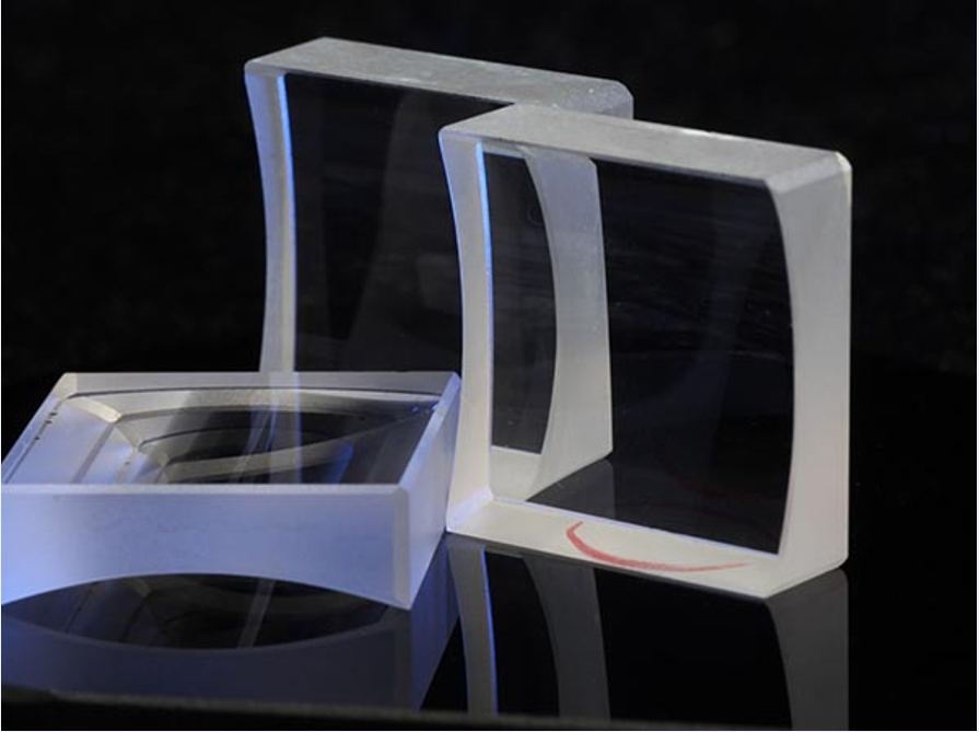
Plano-concave cylindrical lens used as the illustrated workpiece for a project-specific precision optics manufacturing route
Illustrated Workpiece: Plano-Concave Cylindrical Lens
PROJECT-SPECIFIC PROCESS EXAMPLE

Example Plano-Concave Cylindrical Lens Process, Equipment and Metrology Route

This example shows how processing equipment, manufacturing stages and inspection equipment may be coordinated for the illustrated plano-concave cylindrical lens. Each vertical column represents one direct equipment–process–inspection relationship.

Scope note: This is a workpiece-specific route based on the illustrated plano-concave cylindrical lens. It is not a standard process for every optical component. The final route, equipment configuration and inspection plan must be defined according to the material, geometry, incoming condition, target specification and acceptance method.

Scroll horizontally to view the complete route on smaller screens →
PROCESSING
EQUIPMENT
EQUIPMENT 01
Ultra-Precision
Grinding Machine
EQUIPMENT 02
Complex-Surface Bonnet
Polishing Machine
EQUIPMENT 03
Robotic Small-Tool
Polishing Machine
EQUIPMENT 04
Complex-Surface Magnetorheological Finishing Machine
EQUIPMENT 05
Automatic
Cleaning Machine
PROJECT-DEFINED
Alignment and Assembly Equipment
No specific equipment is identified in the source diagram.
PROCESS
STAGE
STAGE 01
Ultra-Precision Grinding Form Generation
STAGE 02
Bonnet Conformal Rapid Polishing
STAGE 03
Small-Tool Polishing
STAGE 04
Magnetorheological Finishing
STAGE 05
Surface Post-Treatment
STAGE 06
Alignment & Assembly
INSPECTION
EQUIPMENT
SHARED: STAGES 01–02
High-Precision Coordinate Measuring Machine
SHARED: STAGES 01–02
High-Precision Coordinate Measuring Machine
STAGE 03
Complex-Surface Profilometer
SHARED: STAGES 03–04
White-Light Interferometer
SHARED: STAGES 03–04
White-Light Interferometer
STAGE 05
Surface Defect Inspection Equipment
STAGE 06
Laser Interferometer
How to read the diagram
Read each column vertically: processing equipment → process stage ← inspection equipment. Blue horizontal arrows show the example process sequence.
Shared inspection categories
Repeated inspection-equipment names show that the same equipment category is associated with more than one process stage. They do not indicate a mandatory quantity.
Equipment reference boundary
Equipment images in the source diagram are functional references only. They do not represent the appearance, manufacturer, model or standard configuration of equipment supplied through APEX.

A component-specific precision optics production line may coordinate ultra-precision grinding, bonnet polishing, robotic small-tool polishing, magnetorheological finishing, surface post-treatment, alignment and optical metrology. The actual equipment and process route are selected only after the workpiece and acceptance requirements have been reviewed.

Discuss a Component-Specific Production Line
Custom Equipment Solutions

For a critical process or production bottleneck, APEX coordinates a suitable platform and necessary configuration changes. Engineering review and agreed sample trials establish the feasible scope.
CUSTOM EQUIPMENT SOLUTION

How a Single-Point Diamond Turning Cell Works

A representative single-point diamond turning cell combines controlled workpiece rotation, a qualified stationary diamond tool, relative machine-axis feed, defined metrology and reviewed process updates. The final platform configuration is selected for the workpiece material, geometry, surface and verification requirements.

Core Single-Point Diamond Cutting Functions

ROTATION

Work Spindle

The work spindle provides controlled workpiece rotation according to the selected machine architecture and qualified process.

COMPONENT

Qualified Workpiece

The workpiece rotates with the spindle. Its material or surface layer, geometry, mounting and incoming condition must be qualified for the intended diamond machining process.

CUTTING

Single-Point Diamond Tool

The diamond tool performs the cutting action without rotating. Tool geometry, orientation and access are selected for the qualified material and target surface.

Relative X / Z Feed

The X direction is radial to the spindle axis, while the Z direction is parallel to the spindle axis. Allocation of motion to the tool and/or workpiece depends on the selected platform.

Work spindle → drives workpiece rotation   |   Diamond tool → cuts the qualified workpiece   |   X / Z feed → controls relative cutting motion

Defined Metrology

  • Measure the workpiece in the agreed state
  • Register measurement data to the defined part datums
  • Validate the measurement method and data

Engineering Review

  • Review the measured result against the agreed target
  • Update the qualified process or tool path where required
  • Re-machine, re-measure and verify as agreed

Axis and feedback boundaries

Use the term “C axis” only when the selected platform provides the corresponding controlled angular-position function. Measurement feedback supports reviewed process or tool-path updates; it does not imply automatic correction.

Functional relationship only — this module is not a machine assembly drawing, scale drawing or representation of one specific Apex model.

  • 01 | When it fits
    More+
    Adding equipment, improving capability or addressing a bottleneck for a defined workpiece and process, where a suitable platform can meet the need with feasible configuration changes.
  • 02 | Information to prepare
    More+
    Material and size, incoming condition, target process and requirements, existing machines/fixtures/metrology, and site constraints.
  • 03 | Feasibility review
    More+
    Assess material/process compatibility, tool/probe access, workholding deformation, operating envelope and measurement capability. Identify risks that require trials.
  • 04 | Platform selection
    More+
    Select a grinding, polishing, ultra-precision machining or metrology platform for the process, workpiece and verification needs. Machine accuracy, repeatability or encoder resolution does not directly establish workpiece form, texture or wavefront performance.
  • 05 | Customization scope
    More+
    Options may include workholding, motion configuration, process modules, software and interfaces. Scope depends on platform limits and engineering feasibility and is confirmed in the technical agreement.
  • 06 | Agreed outputs
    More+
    May include the recommended configuration, necessary changes, limits and interfaces, trial records and acceptance plan. Define workpiece condition, measurement conditions, pass criteria and responsibilities.
     

How Apex Develops Precision Optics Manufacturing Projects

From Requirements Review to Equipment Delivery
Stage Focus
1. Requirements and process review Define the component, incoming condition, goals, measurement method and supply scope; assess feasibility
2. Pre-purchase trial, if agreed Following a successful review, machine and measure samples under a written plan, then confirm results
3. Configuration and equipment purchase Use the review and agreed trial results to confirm configuration, quotation, acceptance and responsibilities before equipment purchase
4. Manufacture and FAT Manufacture equipment under the purchase contract and perform factory acceptance testing (FAT) as agreed
5. Delivery and SAT Provide contracted installation, interface checks, site acceptance testing (SAT), training and support

Plan processing and measurement together, defining requirements, clear aperture, support and environment, measurement methods, uncertainty and decision rules. For acceptance using on-machine metrology, compare with the agreed reference method and assess differences and support effects; correlation alone does not establish interchangeability.

Pre-purchase sample confirmation does not replace contractual FAT/SAT or establish sustained capacity or yield. Trial scope, cost, schedule and decision criteria are agreed separately.

Technical agreements and contracts define supply, integration, performance and service responsibilities.

Precision Optics Manufacturing Solutions FAQ
  • How are project performance commitments defined?
    加 Created with Sketch.
    形状 Created with Sketch.
    Any commitment exists only where stated in the signed technical agreement and acceptance matrix. It is tied to the defined workpiece, incoming condition, process, support, environment, measurement, uncertainty, decision rule and responsibility boundary. Catalog and case-study results are not universal guarantees.
  • Does APEX provide contract optical manufacturing?
    加 Created with Sketch.
    形状 Created with Sketch.
    No. APEX supplies equipment and engineering solutions. A separately approved sample or process trial may support machine selection, feasibility, process qualification or acceptance planning, but it is not a commercial subcontract production service.
  • Can APEX arrange a process trial before purchase?
    加 Created with Sketch.
    形状 Created with Sketch.
    Where technically and commercially feasible, a trial can be considered under a separately agreed scope covering the workpiece, incoming condition, material, quantity, measurement, confidentiality, intellectual property, cost, schedule and decision criteria.
  • What should we send for the first review?
    加 Created with Sketch.
    形状 Created with Sketch.
    Start with the component type, material, dimensions, incoming condition, current process, target specification, expected throughput, available metrology, site constraints and desired supply boundary. Do not send sensitive drawings through the public inquiry form. APEX can identify missing inputs and arrange a secure next step.
  • Can one line process every optical material and geometry?
    加 Created with Sketch.
    形状 Created with Sketch.
    No universal line covers every material and geometry without compromise. Equipment, tooling, process fluids, environment, handling and metrology are selected for a defined component family and qualified process range.
  • Can APEX integrate equipment the customer already owns?
    加 Created with Sketch.
    形状 Created with Sketch.
    Potentially. Existing equipment can be assessed for process capability, interfaces, data compatibility, utilities, documented condition, maintenance status and service support. Reuse, retrofit or integration responsibility is included only after technical review and agreement.
  • Are cleaning, coating and assembly included?
    加 Created with Sketch.
    形状 Created with Sketch.
    They can be included or coordinated when required by the deliverable and expressly listed in the technical agreement. They are not automatic elements of every machining-line project.
  • Does APEX manufacture every machine in a production-line solution?
    加 Created with Sketch.
    形状 Created with Sketch.
    No. APEX is an independent engineering supplier and serves as the coordinated engineering interface within the agreed project scope. Equipment may come from APEX platforms and/or project-evaluated manufacturing resources. The agreement identifies the manufacturer, supplier, interfaces and responsibility for each station.
  • Does “production line” mean a fully automated connected line?
    加 Created with Sketch.
    形状 Created with Sketch.
    Not necessarily. It means a coordinated process-equipment chain. The line may use independent stations, linked cells or automated transfer. The selected automation level depends on the component, process maturity, throughput, handling risk and contracted scope.
  • Is MRF required in every optical manufacturing line?
    加 Created with Sketch.
    形状 Created with Sketch.
    No. MRF is one deterministic corrective-finishing option. Its suitability depends on material compatibility, geometry, initial surface, target error spectrum, metrology and economics. Another project may use conventional or CNC polishing, bonnet correction, ion-beam figuring, plasma-assisted figuring, diamond machining or another qualified process.

Submit Your Precision Optics Manufacturing Requirements

Tell us the project type, target component and current bottleneck so we can help identify the next inputs. Send only a non-sensitive summary initially; exchange detailed technical files through an agreed channel after the initial review.
+86 18115191816​​​​​​​
+86 13921420580​​​​​​​
sales@apex-upt.com​​​​​​​
Contact Us
*
Apex brings together leading industry resources in China and an experienced technical team to deliver precise, reliable, and deployable ultra-precision manufacturing technologies, equipment, and services for advanced industries worldwide.

Quick Links

Products

Contact Us

 Address: S205, Shima Town, Youxian District, Mianyang, Sichuan
 Tel:+86-13921420580
 Whatsapp: +8618115191816
 E-Mail: sales@apex-upt.com
Copyright © 2026 Apex Ultra-Precision Technology (Nanjing) Co., Ltd. All Rights Reserved.  Sitemap  |  Privacy Policy